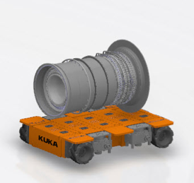
Context: Nowadays in the aeronautical field, factories are using systems to transport the turbofans taking them by the top, the consequences of these systems are difficulties when the line production is changing, they must change all the turbofan transport system. This working group will take example from the best new technologies and available equipments (like Kuka robot) to design a system capable to transport parts of the turbofan between each workstation.
(Collaborative mechanical objective: Design an innovative mobile station capable to transport parts of the turbofan between each workstation permitting more flexibility on the production line)
Systems engineers’ objective: Perform all the automation and control of the system
You will work in perfect collaboration with the Mechanics group.
3D Data:
To achieve your goals and end up having good results, you will work on the following 3D Data:
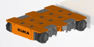
Figure 1 – Omnimove Kuka Robot
This is the Kuka Robot and we want to give it a special role in the Factory. Actually, this robot will supply all the Turbofan assembly line to allow a maximum flexibility.
Your data will depend of the “Collaborative mechanical Design” solutions.
Your work during the following 5 months is design a dynamic model for the entire system which allows transport heavy products:
The system has to be able to reach a precise positioning and move in 2 directions.
To find your Data search on the 3DEXPERIENCE: MECHANICS_Workstation
You will use the CATIA Systems Apps to perform the Logical and regulation part of the system:
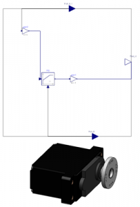
Figure 3 – Example of a mechanical system model in Dymola
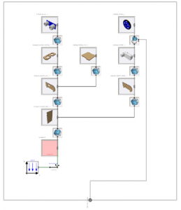
Figure 2 – Example of PID in Dymola Application
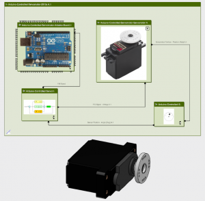
Figure 4 – Example of a complete Logical Structure with its corresponding mechanical model